A coverage map is needed in order to correctly select the right operator. The 4G card eliminates unnecessary interference and communication problems that often occur. Recently, all operators have purchased the card, so it is not surprising that the consumer compares and chooses the best one. Some operators work on the same equipment and their maps are the same, some work separately, since the maps of different operators depend on many factors (including meteorological ones), etc.
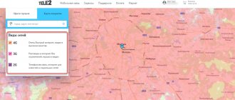
Tele2 coverage areas - 2G, 3G and 4G
Tele2 is one of those mobile operators that is associated with low tariffs and good communication services. Tele2 is a large company, so it is not surprising that its stations are in almost every city, even the smallest. This helps make all communications accessible. The big plus is that Tele2 provides one of the fastest Internet connections.
In which regions is the operator available?
The official distribution area of MOTIV is the Sverdlovsk and Kurgan Regions, Khanty-Mansiysk and Yamalo-Nenets Autonomous Okrug.
In the listed regions, the operator offers cellular and long-distance communications at fixed prices and with per-minute billing, Internet access using 3G and 4G wireless communication technologies (LTE), network setup services and additional equipment designed for both individuals and individuals entrepreneurs and representatives of small, medium and large businesses. The developers offer to study the available offers either on the official website or through the hotline, which is available at 8 800 240 0000.
Beeline coverage areas – 2G, 3G and 4G
Beeline is growing every year and along with it the number of subscribers who use the services of this operator is growing. The main coverage area is around the capital, where the largest number of users is. In all regional centers there is maximum Beeline coverage. Thanks to the modernization of communications, Beeline has reached a new level and now the company has one of the best coverage maps.
MOTIV plans to expand coverage area
Currently, the operator has 3 thousand towers to ensure maximum quality of communication, helps customers in 270 branches and branches, connects new subscribers from partners and at specialized points of sale (as call center operators suggest, the number of such centers has exceeded 2 thousand - and , which means that no one will be left without the Internet or communication with family and friends).
And, although MOTIV’s achievements are visible to the naked eye, the telecommunications operator is in no hurry to dwell on the successes achieved and has already developed a plan to conquer the market of the Tyumen Region. Details of the struggle with the “Big Four” (MTS, MegaFon, Beeline and Tele2) for power are given out in tiny portions, but for those who are eager to understand the situation, it is worth looking at the pages of the official website in the “News” section, and at the same time – on social networks Instagram, VKontakte and Odnoklassniki.
MOTIV is a telecom operator that follows the path of maximum resistance and is available only in the Ural Federal District. The situation will change soon, but how long we will have to wait is unknown.
Helpful 4
Tinkoff 2G, 3G and 4G coverage areas - coverage area map
Tinkoff has one of the largest coverage areas and a high rating. In addition, Tinkoff Mobile has great opportunities to rent dedicated bands from different operators if there are areas that are not covered. Due to this, Tinkoff Mobile can be used where other operators are unavailable. Also, Tinkoff Mobile users can expect regular promotions and discounts.
Beeline coverage map and its features
Having studied the map of the location of the operator’s communication towers, you can see that the entire country is covered by them.
But communication is not always present where there are well-equipped mobile operator stations. Why so, you ask. Many users who do not know about the features of mobile communications attribute problems with it to the service operator. But this is far from true.
Network quality depends on many factors:
- Insufficient signal emission power from the base tower or incorrect direction of the antennas.
- Uneven distribution of base stations due to the peculiarities of the geographical location and architectural development of the settlement, resulting in incomplete coverage of the territory.
- The quality of communication also depends on the density of the area , the layout of the building in which the subscriber is located, or even on the thickness of its walls.
- Weather conditions play an important role - for example, rain greatly affects the throughput of communication channels.
Basically, the subscriber wants to know about the quality of communication and coverage area in the following cases :
- Buying real estate (most often outside the city).
- When going on a trip, picnic or vacation.
- Going on a business trip.
Below you can see the coverage map:
By the way, on the map, large cities are generally shown with the best signal, but remote settlements, so to speak, the outback, cannot boast of this.
But here a surprise may await you - although the tower may not be indicated on the map, the operator’s connection in this area can be quite tolerable.
For what reason does this happen? Most often, a reflected signal is involved in this, although small inaccuracies in drawing up the coverage map cannot be ruled out.
Grand total
In order to be connected, users need to have an idea of the quality of communication in the area where they are located. To do this, the Beeline operator has posted a very accessible map of its network coverage on its website. If the subscriber is not satisfied with the signal quality, the company is always ready to listen and help solve the problem. In addition, today the solution to many connection problems is not limited to adjusting antennas at base stations, but you can find out exactly what solutions to problems exist in this article.
Base station antennas. Let's take a look inside
In cellular communications, sector panel antennas are most often used, which have a radiation pattern with a width of 120, 90, 60 and 30 degrees. Accordingly, to organize communication in all directions (from 0 to 360), 3 (pattern width 120 degrees) or 6 (pattern width 60 degrees) antenna units may be required. An example of organizing uniform coverage in all directions is shown in the figure below:
And below is a view of typical radiation patterns on a logarithmic scale.
Most base station antennas are broadband, allowing operation in one, two or three frequency bands. Starting with UMTS networks, unlike GSM, base station antennas are able to change the radio coverage area depending on the load on the network. One of the most effective methods of controlling radiated power is to control the angle of the antenna, in this way the irradiation area of the radiation pattern changes.
Antennas can have a fixed tilt angle, or can be remotely adjusted using special software located in the BS control unit and built-in phase shifters. There are also solutions that allow you to change the service area from the general data network management system. In this way, it is possible to regulate the service area of the entire sector of the base station.
Base station antennas use both mechanical and electrical pattern control. Mechanical control is easier to implement, but often leads to distortion of the radiation pattern due to the influence of structural parts. Most BS antennas have an electrical tilt angle adjustment system.
A modern antenna unit is a group of radiating elements of an antenna array. The distance between the array elements is selected in such a way as to obtain the lowest level of side lobes of the radiation pattern. The most common panel antenna lengths are from 0.7 to 2.6 meters (for multi-band antenna panels). The gain varies from 12 to 20 dBi.
The figure below (left) shows the design of one of the most common (but already outdated) antenna panels.
Here, the antenna panel emitters are half-wave symmetrical electric vibrators above the conductive screen, located at an angle of 45 degrees. This design allows you to create a diagram with a main lobe width of 65 or 90 degrees. In this design, dual- and even tri-band antenna units are produced (though quite large). For example, a tri-band antenna panel of this design (900, 1800, 2100 MHz) differs from a single-band one, being approximately twice as large in size and weight, which, of course, makes it difficult to maintain.
An alternative manufacturing technology for such antennas involves making strip antenna radiators (square-shaped metal plates), in the figure above on the right.
And here is another option, when half-wave slot magnetic vibrators are used as a radiator. The power line, slots and screen are made on one printed circuit board with double-sided foil fiberglass:
Taking into account the modern realities of the development of wireless technologies, base stations must support 2G, 3G and LTE networks. And if the control units of base stations of networks of different generations can be placed in one switching cabinet without increasing the overall size, then significant difficulties arise with the antenna part.
For example, in multi-band antenna panels the number of coaxial connecting lines reaches 100 meters! Such a significant cable length and the number of soldered connections inevitably leads to line losses and a decrease in gain:
In order to reduce electrical losses and reduce solder points, microstrip lines are often made; this makes it possible to create dipoles and the power supply system for the entire antenna using a single printed technology. This technology is easy to manufacture and ensures high repeatability of antenna characteristics during serial production.
Base stations. General information
This is what cellular antennas look like installed on the roofs of buildings. These antennas are an element of a base station (BS), and specifically a device for receiving and transmitting radio signals from one subscriber to another, and then through an amplifier to the base station controller and other devices. Being the most visible part of the BS, they are installed on antenna masts, roofs of residential and industrial buildings, and even chimneys. Today you can find more exotic options for their installation; in Russia they are already installed on lighting poles, and in Egypt they are even “disguised” as palm trees.
The connection of the base station to the telecom operator’s network can be done via radio relay communication, so next to the “rectangular” antennas of the BS units you can see a radio relay dish:
With the transition to more modern standards of the fourth and fifth generations, to meet their requirements, stations will need to be connected exclusively via fiber optics. In modern BS designs, optical fiber becomes an integral medium for transmitting information even between nodes and blocks of the BS itself. For example, the figure below shows the design of a modern base station, where fiber optic cable is used to transmit data from the RRU (remote controlled units) antenna to the base station itself (shown in orange).
The base station equipment is located in non-residential premises of the building, or installed in specialized containers (attached to walls or poles), because modern equipment is quite compact and can easily fit into the system unit of a server computer. Often the radio module is installed next to the antenna unit, this helps reduce losses and dissipation of power transmitted to the antenna. This is what the three installed radio modules of the Flexi Multiradio base station equipment look like, mounted directly on the mast:
Multiband antennas
With the development of third and fourth generation communication networks, modernization of the antenna part of both base stations and cell phones is required. Antennas must operate in new additional bands exceeding 2.2 GHz. Moreover, work in two and even three ranges must be carried out simultaneously. As a result, the antenna part includes rather complex electromechanical circuits, which must ensure proper functioning in difficult climatic conditions.
As an example, consider the design of the emitters of a dual-band antenna of a Powerwave cellular communication base station operating in the ranges 824-960 MHz and 1710-2170 MHz. Its appearance is shown in the figure below:
This dual-band irradiator consists of two metal plates. The larger one operates in the lower 900 MHz range; above it is a plate with a smaller slot emitter. Both antennas are excited by slot emitters and thus have a single power line.
If dipole antennas are used as emitters, then it is necessary to install a separate dipole for each wave range. Individual dipoles must have their own power line, which, of course, reduces the overall reliability of the system and increases power consumption. An example of such a design is the Kathrein antenna for the same frequency range as discussed above:
Thus, the dipoles for the lower frequency range are, as it were, inside the dipoles of the upper range.
To implement three- (or more) band operating modes, printed multilayer antennas have the greatest technological effectiveness. In such antennas, each new layer operates in a rather narrow frequency range. This “multi-story” design is made of printed antennas with individual emitters, each antenna is tuned to individual frequencies in the operating range. The design is illustrated in the figure below:
As in any other multi-element antennas, in this design there is interaction between elements operating in different frequency ranges. Of course, this interaction affects the directivity and matching of the antennas, but this interaction can be eliminated by methods used in phased array antennas (phased array antennas). For example, one of the most effective methods is to change the design parameters of the elements by displacing the exciting device, as well as changing the dimensions of the feed itself and the thickness of the dielectric separating layer.
An important point is that all modern wireless technologies are broadband, and the operating frequency bandwidth is at least 0.2 GHz. Antennas based on complementary structures, a typical example of which are “bow-tie” antennas, have a wide operating frequency band. Coordination of such an antenna with the transmission line is carried out by selecting the excitation point and optimizing its configuration. To expand the operating frequency band, by agreement, the “butterfly” is supplemented with a capacitive input impedance.
Modeling and calculation of such antennas are carried out in specialized CAD software packages. Modern programs allow you to simulate an antenna in a translucent housing in the presence of the influence of various structural elements of the antenna system and thereby allow you to perform a fairly accurate engineering analysis.
The design of a multi-band antenna is carried out in stages. First, a microstrip printed antenna with a wide bandwidth is calculated and designed for each operating frequency range separately. Next, printed antennas of different ranges are combined (overlapping each other) and their joint operation is examined, eliminating, if possible, the causes of mutual influence.
A broadband butterfly antenna can be successfully used as the basis for a tri-band printed antenna. The figure below shows four different configuration options.
The above antenna designs differ in the shape of the reactive element, which is used to expand the operating frequency band by agreement. Each layer of such a tri-band antenna is a microstrip emitter of given geometric dimensions. The lower the frequencies, the larger the relative size of such an emitter. Each layer of the PCB is separated from the other by a dielectric. The above design can operate in the GSM 1900 band (1850-1990 MHz) - accepts the bottom layer; WiMAX (2.5 – 2.69 GHz) – receives the middle layer; WiMAX (3.3 – 3.5 GHz) – receives the upper layer. This design of the antenna system will make it possible to receive and transmit radio signals without the use of additional active equipment, thereby not increasing the overall dimensions of the antenna unit.