Throughput is a universal characteristic that describes the maximum number of units of objects passing through a channel, node, section. The characteristic is widely used by signalmen, transport workers, hydraulics, optics, acoustics, and mechanical engineering. Everyone gives their own definition. Usually they draw the line by using units of time, clearly linking the physical meaning to the speed of the process. The communication channel transmits information. Therefore, the characteristic of throughput is the bitrate (bit/s, baud).
Unit
Standard bit/s is often supplemented with prefixes:
- Kilo: kbps = 1000 bps.
- Mega: Mbps = 1,000,000 bps.
- Giga: Gbit/s = 1 billion bit/s.
- Tera: Tbit/s = 1 trillion. bps
- Peta: Pbit/s = 1 quadrillion bit/s.
Byte dimensions are used less frequently (1B = 8 bits). The value usually refers to the physical layer of the OSI hierarchy. Part of the channel capacity is taken away by protocol conventions: headers, start bits... Bauds are used to measure the modulated speed, which shows the number of symbols per unit of time. For the binary system (0, 1) both concepts are equivalent. Coding levels, for example, with pseudo-noise sequences changes the balance of power. The baud rate becomes smaller at the same bitrate; the difference is determined by the base of the superimposed signal. The theoretically achievable upper limit of the modulated rate is related to the channel spectrum width by the Nyquist law:
baud ≤ 2 x width (Hz).
In practice, the threshold is achieved by the simultaneous fulfillment of two conditions:
- Single sideband modulation.
- Linear (physical) coding.
Commercial channels show throughput at half the rate. The real network also transmits frame bits, redundant error correction information. The latter applies doubly to wireless protocols and ultra-high-speed copper lines. The headers of each subsequent OSI layer successively reduce the actual channel throughput.
Separately, experts stipulate peak values - numbers obtained using ideal conditions. The actual connection speed is set by specialized equipment, or less often by software. Online meters often show unrealistic values describing the state of a single branch of the World Wide Web. Lack of standardization adds to the confusion. Sometimes bitrate implies physical speed, less often – network speed (subtracting the amount of service information). The values are related as follows:
network speed = physical speed x code speed.
The latter value takes into account the ability to correct errors, always less than one. Network speed is definitely lower than physical speed. Example:
- The network speed of the IEEE 802.11a protocol is 6..54 Mbit/s. Pure bitrate – 12..72 Mbit/s.
- The actual transmission speed of 100Base-TX Ethernet is 125 Mbps, thanks to the adopted 4B5B encoding system. However, the applied NRZI linear modulation technique allows a symbol rate of 125 Mbaud to be specified.
- Ethernet 10Base-T is devoid of error correction code, the network speed is equal to physical speed (10 Mbit/s). However, the Manchester code used determines the assignment of the final symbolic value to 20 Mbaud.
- The asymmetry of the speed of the upstream (48 kbit/s) and downstream (56 kbit/s) channels of a V.92 voice modem is well known. Networks of many generations of cellular communications work similarly.
The channel capacity was named Shannon - the theoretical upper limit of the network bitrate in the absence of errors.
Capacity Enhancement Theory
Information theory was developed by Claude Shannon, observing the horrors of World War II, introduced the concept of channel capacity, and developed mathematical models. Simulation of a connected line includes three blocks:
- Transmitter.
- Noisy channel (presence of an interference source).
- Receiver.
Transmitted and received information is represented by conditional distribution functions. Shannon's capacitive model is described by graphs. The Wikipedia example gives an overview of a medium characterized by five discrete levels of wanted signal. The noise is selected from the interval (-1..+1). Then the channel capacity is equal to the sum of the useful signal and interference modulo 5. The resulting value is often fractional. Therefore, it is difficult to determine the size of the initially transmitted information (round up or down).
Values that are further apart (for example, 1; 3) cannot be confused. Each set formed by three or more distinguishable messages is supplemented by one fuzzy one. Although the nominal capacity of the channel allows 5 values to be transmitted simultaneously, a pair that allows messages to be encoded without errors is effective. To increase the volume, use the following combinations: 11, 23, 54, 42. The code distance of the sequences is always greater than two. Therefore, interference is powerless to prevent the correct recognition of the combination. Multiplexing becomes possible, significantly increasing the throughput of the communication channel.
Five discrete values are also combined by an equilateral graph. The ends of the edges indicate pairs of values that the receiver may confuse due to the presence of noise. Then the number of combinations is represented by an independent set of the composed graph. Graphically, the set is assembled by combinations that exclude the presence of both points of one edge. Shannon's model for a five-level signal is composed exclusively of pairs of values (see above). Attention, question!
- What do complex theoretical calculations have to do with the discussed topic of channel capacity?
The most direct thing. The first digital coded information transmission system, the Green Bumblebee (World War II), used a 6-level signal. The theoretical calculations of scientists provided the allies with reliable encrypted communications, allowing them to hold over 3,000 conferences. The computational complexity of Shannon graphs remains unknown. They tried to obtain meaning in a roundabout way, continuing the series as the case became more complex. We consider the Lovas number to be a colorful example of what has been said.
What to choose?
Based on the above arguments and facts, we can draw an unambiguous conclusion: a non-guaranteed channel is completely unsuitable for a modern developing web project.
The pricing policy of many Internet service providers offering connection via a non-guaranteed channel seems dishonest: the stated speeds are almost never achieved in reality, and information about overpayments and traffic restrictions is very often not communicated to the client in clear text. Finally, in our time, when the share of “heavy” multimedia content makes up the majority of global Internet traffic, choosing a non-guaranteed channel seems a rash and short-sighted step.
The distinctive features of a guaranteed channel are stability, as well as an honest and transparent pricing policy: you will always have a connection at a guaranteed speed for a fixed amount. The cost of connecting via a guaranteed channel fully pays for itself as the project develops and expands.
Readers who are unable to leave comments here are invited to join us on the blog.
Bitrate
The capacity of a real channel is calculated according to theory. A noise model is constructed, for example, additive Gaussian, and the expression of the Shannon-Hartley theorem is obtained:
C = B log2 (1 + S/N),
B – bandwidth (Hz); S/N – signal/noise ratio. The base 2 logarithm allows you to calculate the bitrate (bit/s). The magnitude of the signal and noise are written in square volts or watts. Substituting decibels gives the wrong result. The formula for peer-to-peer wireless networks is slightly different. Take the spectral density of the noise multiplied by the bandwidth. Separate expressions for fast and slow fading channels are derived.
Multimedia files
In relation to entertainment applications, bitrate shows the amount of information stored and played back every second:
- Data sampling rates vary.
- Samples of different sizes (bits).
- Sometimes encryption is carried out.
- Specialized algorithms compress information.
A golden mean is selected that helps minimize the bitrate and ensures acceptable quality. Sometimes compression irreversibly distorts the source material with compression noise. Often the speed shows the number of bits per unit of time of audio or video being played (displayed by the player). Sometimes the value is calculated by dividing the file size by the total duration. Since the dimension is specified in bytes, a multiplier of 8 is entered. Often the multimedia bitrate fluctuates. The entropy rate is called the minimum rate that ensures complete preservation of the original material.
CDs
The audio CD standard requires the stream to be transmitted at a sampling rate of 44.1 kHz (16-bit depth). Typical stereo music is composed of two channels (left, right speakers). Bitrate doubles to mono. The throughput of the pulse code modulation channel is determined by the expression:
- bitrate = sampling rate x depth x number of channels.
The audio CD standard gives a final figure of 1.4112 Mbit/s. A simple calculation shows: 80 minutes of recording takes up 847 MB, excluding headers. The large file size determines the need to compress the content. Here are the MP3 format numbers:
- 32 kbit/s – acceptable for articulate speech.
- 96 kbps – low quality recording.
- .160 kbit/s is a weak level.
- 192 kbps is something in between.
- 256 kbps is typical for most tracks.
- 320 kbps – premium quality.
The effect is obvious. Reducing speed while increasing playback quality. The simplest telephone codecs take 8 kbit/s, Opus - 6 kbit/s. Video is more demanding. A 10-bit uncompressed Full HD stream (24 frames) takes up 1.4 Gbps. The need for providers to continually exceed previously set records becomes clear. Basic family Sunday viewing is measured by the overall experience of the audience. It is difficult to explain to loved ones what an error in image digitization is.
Real channels are being built, providing a solid supply. Similar reasons are behind the progress of digital media standards. Dolby Digital (1994) clearly provided for information loss. The first showing of Batman Returns (1992) was played from 35mm film carrying compressed audio (320 kbps). The video frames were transferred by a CCD scanner, and the equipment unpacked the audio along the way. Equipped with a 5.1 Digital Surround system, the hall required further digital processing of the stream.
Real systems are often formed by a set of channels. Today, the former chic is being replaced by Dolby Surround 7.1, and Atmos is growing in popularity. Identical technologies can be implemented in almost original ways. Here are examples of eight-channel (7.1) audio:
- Dolby Digital Plus (3/1.7 Mbps).
- Dolby TrueHD (18 Mbit/s).
The specified bandwidth varies.
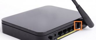
How to set or change channel width on a router
Any router can broadcast in 2.4 GHz mode. Most modern devices also support 5 GHz operation. Few wireless standards work only in this range, but they are also backward compatible with 2.4 GHz gadgets. Before specifying the bandwidth, you should pay attention to the Wi-fi specification in the settings. The wrong communication standard may make the desired frequency band configuration unavailable.
The location of the channel width, channel number and wireless communication standard parameters in the router configuration depends on the firmware version.
Old equipment may not have Internet access after setup if the Wi-Fi channel width is 40 MHz or more. If the router is not operating in the appropriate mode, devices are able to recognize the network without actually accessing it. This connection is only suitable for exchanging system data between the router and the device.
To change the bandwidth value, you first need to open the router settings. To do this, you need to connect it to the system unit, turn it on and enter the device’s IP address in the address bar. It is usually listed along with the default username and password on the bottom or back of the case.
Bandwidth settings are determined by the router model, firmware version and localization. The Channel Width or Bandwidth parameters may also be named Channel Width and Bandwidth.
TP-Link
To set the Wi-Fi channel width in the TP-Link interface, you need to go to the “Wireless Mode” tab in the menu on the left, and select “Wireless Mode Settings”.
Asus
The frequency range configuration for devices from this company is located in the “Wireless Network” item in the “Advanced Settings” list.
Zyxel Keenetic
The channel width settings for Zyxel Keenetic routers are located on the Wi-Fi tab.
In some versions of this interface, network bandwidth can be set in the advanced settings of the Home Network tab.
Keenetic
To specify the Wifi channel width in modern Keenetic routers, you will need to go to the “Home Network” tab in the “My Networks and Wi-Fi” section.
Each frequency range has an "Advanced Settings" link. By clicking on it, you can set the bandwidth and other Wifi parameters.
D-link
To select the amount of bandwidth in D-Link devices, you will need to go to the “Advanced Settings” item in the Wi-Fi menu.
Channel Capacity Examples
Let's consider the evolution of digital information transmission technologies.
Modems
- Acoustic pair (1972) – 300 baud.
- Modem Vadik&Bell 212A (1977) – 1200 baud.
- ISDN channel (1986) – 2 channels 64 kbit/s (total speed – 144 kbit/s).
- 32bis (1990) – up to 19.2 kbit/s.
- 34 (1994) – 28.8 kbps.
- 90 (1995) – 56 kbit/s downstream, 33.6 kbit/s upstream.
- 92 (1999) – 56/48 kbps downstream/upstream.
- ADSL (1998) – up to 10 Mbit/s.
- ADSL2 (2003) – up to 12 Mbit/s.
- ADSL2+ (2005) – up to 26 Mbit/s.
- VDSL2 (2005) – 200 Mbit/s.
- fast (2014) – 1 Gbit/s.
Ethernet LAN
- Experimental version (1975) – 2.94 Mbit/s.
- 10BASES (1981, coaxial cable) – 10 Mbit/s.
- 10BASE-T (1990, twisted pair) – 10 Mbit/s.
- Fast Ethernet (1995) – 100 Mbit/s.
- Gigabit Ethernet (1999) – 1 Gbit/s.
- 10 Gigabit Ethernet (2003) – 10 Gbit/s.
- 100 Gigabit Ethernet (2010) – 100 Gbit/s.
WiFi
- IEEE 802.11 (1997) – 2 Mbit/s.
- IEEE 802.11b (1999) – 11 Mbit/s.
- IEEE 802.11a (1999) – 54 Mbit/s.
- IEEE 802.11g (2003) – 54 Mbit/s.
- IEEE 802.11n (2007) – 600 Mbit/s.
- IEEE 802.11ac (2012) – 1000 Mbps.
cellular
- First generation: NMT (1981) – 1.2 kbit/s.
- GSM CSD, D-AMPS (1991) – 14.4 kbit/s.
- UMTS-FDD (2001) – 384 kbit/s.
- IEEE 802.16e (2007) – 144/35 Mbit/s.
- LTE-A (2012) – 115 Mbit/s.
Japan today is introducing the fifth generation of mobile communications, increasing the capabilities of transmitting digital packages.
Signal transmission methods
Today, there are three main ways to transmit signals between computers:
- Transmission over radio networks.
- Data transmission via cable.
- Data transmission via fiber optic connections.
Each of these methods has individual characteristics of communication channels, which will be discussed below.
The advantages of transmitting information via radio channels include: versatility of use, ease of installation and configuration of such equipment. Typically, a radio transmitter is used to receive and transmit data wirelessly. It can be a modem for a computer or a Wi-Fi adapter.
The disadvantages of this transmission method include unstable and relatively low speed, high dependence on the presence of radio towers, as well as the high cost of use (mobile Internet is almost twice as expensive as “stationary” Internet).
The advantages of data transmission via cable are: reliability, ease of operation and maintenance. Information is transmitted through electric current. Relatively speaking, a current at a certain voltage moves from point A to point B. A is later converted into information. The wires can withstand temperature changes, bending and mechanical stress very well. The disadvantages include unstable speed, as well as deterioration of the connection due to rain or thunderstorms.
Perhaps the most advanced data transmission technology at the moment is the use of fiber optic cable. Millions of tiny glass tubes are used in the design of the communication channels of the communication channel network. And the signal transmitted through them is a light pulse. Since the speed of light is several times higher than the speed of current, this technology has made it possible to speed up the Internet connection several hundred times.
The disadvantages include the fragility of fiber optic cables. Firstly, they cannot withstand mechanical damage: broken tubes cannot transmit a light signal through themselves, and sudden temperature changes lead to their cracking. Well, the increased background radiation makes the tubes cloudy - because of this, the signal can deteriorate. In addition, the fiber optic cable is difficult to repair if it breaks, so it has to be completely replaced.
The above suggests that over time, communication channels and networks of communication channels are improved, which leads to an increase in data transfer rates.