Over the weekend, a friend brought me an explay surfer 8.31 3g tablet. When dropped from the table, the back cover of the tablet opened, pulling the SIM card inserted into the slot. Alas, such situations with your favorite gadgets have probably happened to many of you. However, if you really want to, this problem can be solved on your own.
As you can see in the photo, the slot's attachment point has been torn out, on one side, along with the foil taped to the board (blue circle). It’s good that this section of foil is not a track and you can safely put it in place (glue it).
The red circle marks the broken legs of the slot and their remains on the tablet board.
Even upon inspection, it was discovered that the SIM card was not fixed, that is, the slot itself was damaged. Of course, I would replace it with another one, but the nearest specialized store where you can purchase a slot is 150 km away. Having learned about this, a friend asked me to remove the lock and put the slot as it is (remove the spring so that the SIM card does not come back out). But I couldn’t just pull out these parts, because if I need to change the SIM card later or, for example, I have to open the case, I can’t do without breaking out the slot again.
The photo (after repair) shows that on this tablet model, the SIM card is inserted deeply and is almost impossible to pull out without an ejector mechanism.
Thus, I had to repair the slot itself first.
Parts, tools and consumables
The procedure itself is not that complicated, but it requires tools and materials.
SIM connectors
They are not inferior to USB connectors in terms of variety. In addition, some of them are located in the same housing with SD card slots. Usually sellers in radio stores sell such spare parts individually, but you can buy a whole set on AliExpress.
There are never any extra parts, and besides, there will be spare parts in case of repeated malfunction.
Tools and tweezers
You definitely need at least simple tweezers. We will use it to remove the broken connector from the board. To resolder the connector reliably and efficiently, you need a soldering station or soldering iron and a hair dryer with temperature control.
Consumables
You will need aluminum tape, paste-like flux, and solder. If there are difficulties in replacement, Rose's alloy will also come in handy. To clean the board after soldering work, you will need isopropyl alcohol (isopropanol) or Galosh.
Replacing the slot itself
Naturally, slots from different manufacturers, and even from different models, differ significantly from each other. Not in terms of design or technical meaning, but in terms of form factor.
Therefore, before embarking on such a situation, it is extremely important to purchase components that will definitely suit your smartphone. Always buy several slots, not just one (by duplicating components, you minimize the risk of defects).
You can use both an ordinary soldering iron and a soldering station with a hair dryer. We warm up the pads and use tweezers to lift the non-working slot (use flux). Having tinned the sites, we install a new analogue. You may have to pre-bend the slot pins so that they fit perfectly onto the board pads.
The video shows how to replace the SIM card slot on the Galaxy Mini 2 GT-S6500:
Tweet
Soldering technique and its subtleties
As an example, consider a problem with the Fly smartphone.
This smartphone has already had a replacement board with SIM connectors, but they are broken again. A common cause of malfunction is when the smartphone does not see the SIM card. One of the connectors is missing a central contact, the second was even more damaged.
In the photo, one of the two SIM connectors has already been replaced and the second one is warming up.
It is important to evaluate the soldering location. If soldering occurs on a massive metal substrate, the board will transfer the incoming heat from the hair dryer and will not heat up. This is the main mistake beginners make. Therefore, when replacing connectors, inexperienced craftsmen immediately set temperatures above 350 °C. The solder itself begins to melt from 180 ℃ to 230 ℃ (lead-containing solders) or from 180 to 250 ℃ (lead-free solders).
And when the board is heated to the conventional melting temperature of the solder, the part itself or the connector, or the top layer of the board is affected by a much higher temperature. Therefore, it is best to place the board on a wooden board with several layers of napkins on it. There should also be few of them (the surface will no longer be smooth, which in turn will lead to poor surface tension of the solder). Wood and paper heat up much earlier and release less heat into the environment.
Additionally, you need to install a radiator (for example, a coin, or you can get by with thermal tape, aluminum tape). We set the hair dryer at 100 - 150 ℃ and maximum air flow (I have a Lukey 702 station).
Warm up the board for 2-3 minutes. Then, we increase the temperature to 250-290 ℃ and slightly reduce the air flow. After just 10-30 seconds, the soldering area will be at the melting point of the solder. If this does not happen, you need to wait a little longer or raise the temperature by 10 - 20 ℃. You need to remove the connector with tweezers carefully so as not to touch the SMD components.
As a result, the broken connector is soldered intact and without overheating.
Next, we prepare the soldering area. We solder the contact pads, add a little flux and solder.
We install a new connector and solder it using exactly the same principle. First, 100 - 150 ℃ with maximum air flow for a minute or two. Then, reduce the flow a little and raise the temperature to 250 - 290 ℃. The connector begins to be soldered in (this is noticeable by the glare of the solder), press it down a little with tweezers.
After the hairdryer is finished, you need to additionally solder the contacts.
And a little more about soldering
By the way, the board itself with the SIM connector also has a metal substrate, but this is not a reason to increase the temperature to 400 ℃. It's just that the soldering time is a little higher, which is not very important.
And a test with a SIM card.
Removing SIM holder debris
Now comes the fun part. Isn’t it important for us to maintain the readability of SIM and SD cards? A stupid question, of course, but now you have to imagine that the contacts in the reader are like hooks. And when you pull out a piece of the slot, it will actively cling to these hooks. And it’s easier to break them off. Here is an example of a broken holder.
Our task is to ensure that the debris slides over these hooks. Everything inside looks something like this.
And thick film will help us with this. It must be cut to the width of the slot. The length is at your discretion. If only it was comfortable for you to hold it.
We insert the film up to the fragment and try to bring it under it. You can help with the rest of the slot. He will press the film together with the contacts. Basically, the preparation is over.
Now, using needles, carefully push the fragment out. Control the position of the contacts so that debris does not cling to them.
Personally, it took me about 20 minutes to pull out the fragment, but nothing was damaged.
What to do if there are microcircuits nearby
There are several solution methods. Either install radiators on the chips and protect them with metal tape, or use bottom heating up to 200 ℃. This problem is relevant for those devices that have a high layout of radio components on the board. For example, Samsung or iPhone flagships. On the iPhone there is usually a modem nearby, which is made in the form of a BGA chip. You can also accidentally heat up the processor, which you will get tired of rolling.
Therefore, evaluate your strength before replacing connectors yourself. There is also a more radical option - mechanical removal of the old connector. But this method is very dangerous because you can hit the tracks or unintentionally cut off other parts.
Reassembly after repair
Before assembly, check the condition of the charging connector. If the soldering on the tracks is broken, it must be restored. Otherwise, the phone will not charge or transfer data to the computer. Hello Samsung engineers. If there is no doubt, then assemble the phone in reverse order.
Be careful when inserting the top of the board. You need to squeeze the SIM tray eject mechanism. Otherwise the board will not fit into place. Next, tighten all the screws and turn on the phone for a full check. Have you connected all the connectors?
Well, it is advisable to additionally seal the back cover with some kind of sealant. I used b5000. Or heat it well and squeeze it tightly. If you removed it carefully, then the factory tape will be enough.
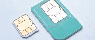
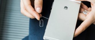
Remove the SIM card from the slot of the Xiaomi Redmi 4 smartphone, what could be easier?
We recently showed a tablet where we managed to put as many as 3 cards and a HYUNDAI DVD player into the microSD slot, which became a changer at the behest of the children :)
Today we also have a non-standard situation, the owner did not deal with slots for micro and nanosim cards and, without noticing that the SIM card tray had already been removed, inserted a full-fledged SIM card from an old smartphone into the slot. The card successfully entered the slot and upon further attempts to get it out, it fell even further.
Bottom line
This article discussed in detail how you can change the SIM connector yourself and at home. The main thing is not to rush while soldering. and carefully remove the connectors so as not to destroy small SMD parts. Practice on donor boards before performing repairs on a faulty device.
Replacing the SD card slot is similar to replacing the SIM connector.
Also, replacing parts on a smartphone is not much different from tablets. The main difference is the dimensions and layout of the devices.
How much does the work cost?
Generally. the price starts from 600 rubles, and depends on the complexity of replacing and disassembling the device. The price is also affected by the availability of parts and the warranty provided by the service center.
Disassembling the Samsung A520 smartphone
So let's get started. First, you need to thoroughly heat the back cover. You need to pry it with something very sharp and strong. I used a scalpel and a wide spatula. The lid is easy to break, so take your time. And do not insert the tool deeply, so as not to damage the NFC. Maximum 7-8 mm. Ideally, go through it and fix it with something, then continue heating it. You can also heat it with a household hairdryer, if it is of high quality.
Let's say the back cover has been peeled off. Next we see black plastic panels with the same NFC cable in the middle. Unscrew all the screws and pull out both panels. Pry it carefully, try not to tear or break anything. Then make sure both SIM holders are pulled out. Disconnect all visible connectors, starting with the battery connector. You can do it with your fingernail, but most importantly, not with a metal object.
Now you need to pull out the board. You need to pry it off carefully from the top edge. It is more convenient to do this with a spatula. In several places. You didn't forget to unscrew the three black screws, did you? One near the battery connector, two fix the charging connector.
SIM card under bolts
Sometimes memory card slots are hidden under bolts. You will have to unscrew some part of the smartphone case to get to them. Such methods are usually typical for specialized smartphones that are protected from moisture, dust, shockproof, etc.
Here is an example of one such device and what it looks like.
It is easy to identify it, firstly, by appearance. Secondly, if the first and second methods do not suit you, you should look for the part that can turn away from your gadget. You can first look at the instructions for your model. There might be a clue there too.